Москва, Игарский проезд, д. 2, офис 314
схема проезда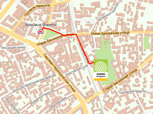
тел. (495) 639-80-82
ИНН: 7703741816
КПП: 771601001
HW-133-v1.0 DC-DC Step-Down (Buck) Converter module, typically based on the high-frequency switching regulator chip
The HW-133-V1.0 uses a minimal-component layout to achieve its small footprint ( ). Description IN+ Positive supply voltage ( 4.5V4.5 cap V – 28V28 cap V ) IN- Ground / Negative supply OUT+ Regulated positive voltage output OUT- Ground / Negative output (Common with IN-) Hw-133-v1.0 Datasheet
Output Voltage: Adjustable from 0.8V to 20V via an onboard potentiometer. HW-133-v1
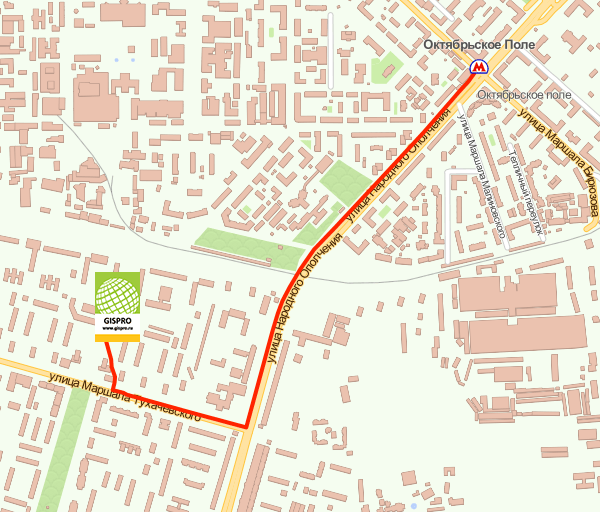
Москва, Игарский проезд, д. 2, офис 314
схема проездател. (495) 639-80-82
ИНН: 7703741816
КПП: 771601001